Chapter 3: Index Buffer Objects and Primitive Types
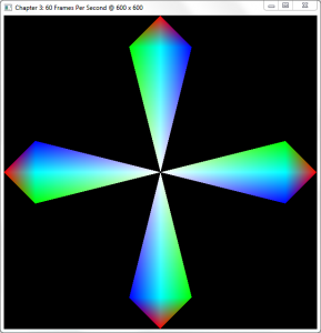
Now that we’ve drawn our first geometric shapes in Chapter 2, it’s time to step up the complexity a bit. While uploading our vertices to the GPU and rendering them all as a batch is a great solution for a single triangle, you will soon notice that as geometric complexity increases, so does the need for more efficient rendering methods.
In this chapter, you’ll learn how to:
- Use index buffers (AKA Index Buffer Objects, or IBOs).
- Draw complex geometry easier.
- Use several more primitive types.
Please note that this chapter builds on the samples provided in Chapter 2, so if you haven't read it, I suggest you read it now
Check the requirements before continuing
This chapter is 100% compatible with OpenGL 3.x level hardware by changing only a few lines of code.
The Problem
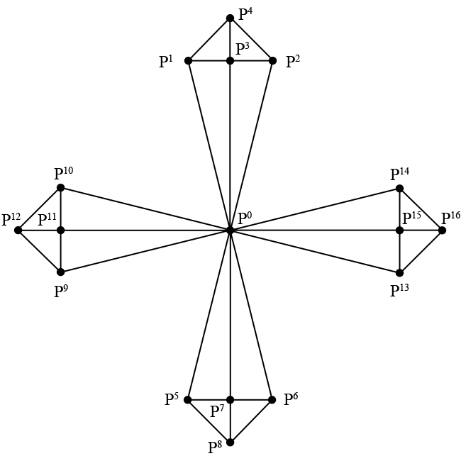
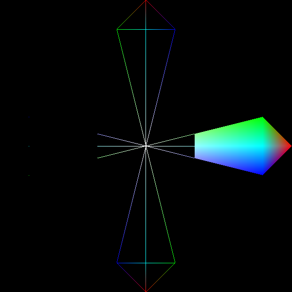
Let's say we wanted to draw the following shape onto the screen, each of the spoke’s vertices (marked by Pn) a different color:
Using GL_TRIANGLES
If we were to use the previous chapter’s code, we’d have to draw out 16
individual triangles composed of 48 vertices in total using the GL_TRIANGLES
primitive type since we describe each triangle separately. This means that each
set of three vertices in your array describes a single independent triangle. You
can see an example of this in file chapter.3.0.1.c in the download section at
the end of this chapter.
In this example, P0 (origin) is duplicated 8 times in total, the center vertices P3, P7, P11, and P15 are duplicated 4 times each. If this seems like overkill to you for such a simple shape, you’re right; there are better ways of describing it.
Amount of data sent to GPU memory using GL_TRIANGLES:
(size of Vertex) 32 bytes x 48 = 1,536 bytes.
Using GL_TRIANGLE_STRIP

The GL_TRIANGLE_STRIP primitive mode is a bit better when it comes to sheer
number of vertices sent to the GPU, since we only send 28 in total. However,
there’s still unneeded duplication, and the way in which we traverse the
vertices is a bit cumbersome due to the way that GL_TRIANGLE_STRIP works.
The GL_TRIANGLE_STRIP primitive type creates triangles out of every newly
added vertex and its preceding two vertices. In the animation, P0 to
P1 doesn’t yield a triangle, but after we add P3, a
triangle forms. Each vertex after the addition of P3 yields a new
triangle.
In addition to the unneeded duplication (notice P3 → P4 → P3) and the amount of data sent over, there’s also no way of changing the order in which we draw the vertices besides uploading a completely new batch of data.
Amount of data sent to GPU memory using GL_TRIANGLE_STRIP:
(size of Vertex) 32 bytes x 28 = 896 bytes.
Enter Index Buffers
So far, we’ve been drawing our geometry with a call to glDrawArrays, which
simply draws a certain subset of elements from the currently active vertex
buffer object. Let’s explore a new way of drawing by walking through some new
code. Make a copy of chapter.2.4.c from the previous chapter and name it
chapter.3.1.c.
Since we’re in chapter two of the book, change the WINDOW_TITLE_PREFIX
pre-processor definition to reflect Chapter 3.
Next, change CurrentWidth to have an initial value of 600:
Add a new identifier named IndexBufferId to our list of global identifier
variable declarations:
Remove the call to glDrawArrays in RenderFunction and replace it with the
following line:
Here’s the big change, change the Vertices variable in CreateVBO to the following:
Immediately beneath Vertices, add the following array definition:
At the end of the CreateVBO function, right below the last call to glEnableVertexAttribArray, add the following lines of code:
Finally, add the following lines of code between the glDeleteBuffers and glBindVertexArray lines of the DestroyVBO function:
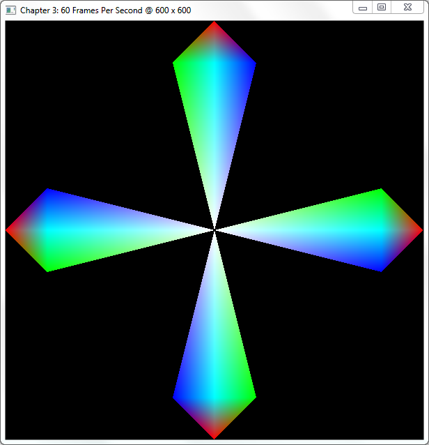
Your output should look like:
Step-By-Step
If you’ve analyzed the code a bit, you’ll notice that we upload each vertex exactly once to the GPU instead of 48 vertices including duplicates. Let’s walk through the code and take a good look at what we did here.
The first changes were purely aesthetic: as always, we changed the window title to reflect this chapter and made the window a perfect square for the geometry to show up symmetrical. In the next chapter, we’ll introduce a method that doesn’t require you to reshape your window to achieve symmetry.
The next thing we add is the IndexBufferId variable to the global list of
variables. This variable will hold the buffer’s identifier generated by a call
to glGenBuffers, similar to vertex buffer generation in the previous chapter.
Modifying Vertices and Adding Indices
After that, we modify the CreateVBO function and replace its Vertices array
with an array of 17 total vertices. If we were to use glDrawArrays on this VBO
without indices, we would not output the desired shape as illustrated earlier.
Instead, we have to define one more array, named Indices, to hold the indices
of the elements in Vertices in drawing order.
For example, the first three indices 0, 1, and 3, correspond directly with the
first, fourth, and second elements in the Vertices array, composing the
left-bottom triangle of the shape’s top spoke. In total, we upload 48 indices
since each spoke consists of four triangles (3 x 4 x 4).
Indices is defined as a GLubyte array of 48 elements; GLubyte is the
OpenGL data type for an unsigned byte (unsigned char). You could use any of
the following unsigned integral OpenGL data types: GLubyte, GLushort, and
GLuint, since indices are never negative (signed) or fractional
(float/double).
Index Buffer Generation, Binding, and Filling
The final thing inside of the CreateVBO function is to generate the actual
index buffer with a familiar call to the glGenBuffers, nothing new there. It
isn’t until the next function call to glBindBuffers that we specify a brand
new target that we haven’t used before.
Until now, we’ve only supplied the GL_ARRAY_BUFFER target to glBindBuffer to
specify that the buffer is an array of vertices. While we still upload our
vertices in this manner, our newly generated buffer is bound to the
GL_ELEMENT_ARRAY_BUFFER target that allows us to specify which vertices in the
active GL_ARRAY_BUFFER we’re using.
The call to glBufferData should also look very similar to last chapter’s code;
we introduce no new options here besides the usage of the
GL_ELEMENT_ARRAY_BUFFER target flag.
Rendering the Indexed Vertex Buffer Object
In the code, we removed the call to glDrawArrays and replaced it with a call
to a function called glDrawElements. Whereas glDrawArrays only draws the
active GL_ARRAY_BUFFER, glDrawElements draws the indices of the active
GL_ARRAY_BUFFER as specified by the buffer bound to the
GL_ELEMENT_ARRAY_BUFFER target. Let’s take a closer look at the
glDrawElements function:
The first parameter, mode, takes in the primitive mode to use such as
GL_TRIANGLES or GL_TRIANGLE_STRIP; the same as the mode parameter of
glDrawArrays.
The second parameter, count, specifies how many elements in total to draw. In
our case, this value is 48 since that’s the amount of indices in the Indices
array.
The third parameter, type, specifies which data type was used for the index
array. In our case, this is GL_UNSIGNED_BYTE, since we used the GLubyte data
type to construct the Indices array. Please note that this type must
reflect the data type used to construct the array containing the indices.
The fourth and last parameter, indices, specifies the offset in bytes in the
index array of where we want to start rendering, allowing us to render subsets
of the vertex data. For example, if we wished to draw just the right-hand spoke
of the shape, we’d call the glDrawElements function with the following parameters:
In this function call, we draw 12 vertices starting at index offset 36 of the
index buffer, corresponding to the vertices in the Indices array. Make sure to
change the parameters in glDrawElements according to the type of index buffer
you're using. For example, if we were to use an index buffer containing unsigned
integers (GLuint), we'd have to change the above function call to the
following:
Amount of data sent to GPU memory using Index Buffers:
(size of Vertex) 32 bytes x 17 + 1 GLubyte x 48 = 592 bytes.
Swapping Index Buffers
Sometimes it is not possible to avoid having to change the indices you wish to
render, in which case it is possible to swap the active index buffer by simply
changing the buffer bound to the GL_ELEMENT_ARRAY_BUFFER target.
Make a copy of chapter.3.1.c rename it to chapter.3.2.c and open it up in your
editor. The first thing we do is change the block of global GLuint variable
definitions to look like this:
Next, add the following function declaration right underneath the IdleFunction
function declaration:
In the InitWindow function definition, add the following line underneath the
call to glutCloseFunc:
Add the following function definition right below the InitWindow function
definition:
Next, we need to make some changes to the rendering, RenderFunction, to
facilitate the changes we've made. Replace the call to glDrawElements with the
following code:
Inside of the CreateVBO function right underneath the Indices array
definition, place the following code:
Inside of the same function, change the call to generate the index buffers to the following:
Immediately after that, change the glBindBuffer function call to the
following:
Right before the call to glGetError, add the following block of code:
Finally, in the DestroyVBO function, change the glDeleteBuffers call with
IndexBufferId as its parameter to the following:
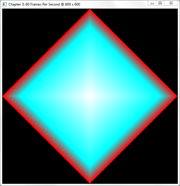
When you run the program and press the "T" key, you are able to toggle back and forth between the original shape and this new shape:
Step-By-Step
With only a few minor changes, we were able to draw an entirely new shape out of he same set of vertices. The only thing we did to achieve this was swap the index buffers. If you examined the code, you’ll notice that we’ve covered all of the functionality used in this sample before, so we’ll just glance over some of the highlights.
In this sample, we changed the amount of index buffers generated to two to
contain an alternate index buffer for our swapping purposes. In the CreateVBO
function, we updated glGenBuffers to generate two buffer objects and store
their identifiers in the array IndexBufferId, which now contains two elements.
After that, we upload the new indices stored in AlternateIndices to the GPU’s
memory using glBufferData as usual and set the current active index buffer
back to the original.
We also added some new FreeGLUT functionality for handling keyboard input:
The Key parameter contains the character representation of the key pressed,
while the X and Y parameters contain the mouse positions relative to the
window at the time of the key-press. The only thing we do in this function is
toggle back and forth between index buffers while retaining the same vertex
data.
We register the call to this function in the InitWindow function with a call
to glutKeyBoardFunc, which takes in as its only parameter a function pointer,
just as any other FreeGLUT callback functions do.
More Primitive Types
Until now, we’ve only discussed GL_TRIANGLES and GL_TRIANGLE_STRIP as
methods to describe geometry. However, there are several more so-called
"primitive types" available in OpenGL, each of which alters the output in a
different way. In this section, we’ll discuss a few more.
A "primitive" is the smallest component of a geometrical shape. So far, we’ve used triangles as our primitive types but OpenGL supports two others: points and line segments.
GL_POINTS
The first and simplest primitive type is GL_POINTS, where each vertex
specifies a visible point in space. When using GL_POINTS, OpenGL will draw
simple points onto the screen. For example, change the glDrawElements in
chapter.3.1.c to use GL_POINTS instead of GL_TRIANGLES, and each vertex
will show up as a colored one-pixel point.
You can change the point-size with the function glPointSize, which simply
takes in a single parameter, size, specifying the size of the points as a
floating-point number.
GLLINESTRIP
The second primitive type is GL_LINE_STRIP, which allows us to draw lines
between vertices. GL_LINE_STRIP works much like GL_TRIANGLE_STRIP, where
each new vertex adds to the overall line instead of defining a brand new line
every two vertices.
To try this primitive type, add one more index to 0 at the very end of the index
array named Indices in chapter.3.1.c, and change the call to glDrawElements
to the following:
You should now see the outline of the shape described at the beginning of the chapter.
GL_LINE_LOOP
The third primitive type, GL_LINE_LOOP is very similar to GL_LINE_STRIP with
the exception that it closes the line segment by drawing a line between the last
vertex and the first. Whereas we added one more index to Indices for
GL_LINE_STRIP, we would not have to do this with GL_LINE_LOOP.
GL_LINES
GL_LINES is to lines what GL_TRIANGLES is to triangles, meaning that
GL_LINES describes separate, unconnected lines. However, since a line consists
of two points instead of the three required by a triangle, changing the sample
in chapter.3.1.c does not yield a desired result. We would have to modify the
index array extensively in order to get the correct results.
GL_TRIANGLE_FAN
The last primitive type to discuss in this section is GL_TRIANGLE_FAN, a close
relative to the well-known GL_TRIANGLE_STRIP. Whereas GL_TRIANGLE_STRIP
constructs a new triangle by connecting the last three points added to the list,
GL_TRIANGLE_FAN constructs a new triangle from the very first point and the
last two points added, resulting in a fan-like shape. This means that every new
triangle is connected to the very first added to the list.
There is no correct way of drawing the shapes presented in this chapter using
GL_TRIANGLE_FAN, but this primitive type is useful for drawing center-oriented
polygons, such as a pentagon with all of its vertices connecting in the center.
Polygon Rasterization Modes
If you’re looking to display your geometry as a wireframe of its original,
there’s no need to change its primitive type. The function glPolygonMode can
take care of this by changing the method used to fill the triangles, a process
called “rasterization” that we’ll explore in a future chapter:
The function’s first parameter, face, specifies which polygons of your
geometry the function affects. As of OpenGL 3.0, this parameter may only be
set to GL_FRONT_AND_BACK; we’ll learn more about front- and back-faces in a
future chapter.
The function’s second parameter, mode, specifies how the polygons are
rasterized. This mode can be set to one of the following values:
GL_POINTDraws the geometry as points, related to theGL_POINTSprimitive type.GL_LINEDraws the geometry as lines (wireframe), related to theGL_LINESprimitive type.GL_FILLThe default: draws each triangle filled with a solid color.
Below follows a combination of three screenshots showing all of the different rasterization modes for the example shown earlier in this chapter:
Conclusion
Index Buffer Objects can be incredibly useful when dealing with complex shapes by limiting the amount of data sent to the GPU. The fact that many model formats provide their data in separate vertex and index sections only makes the decision to use index buffers more natural.
In upcoming chapters, index buffers are the primary method to describe geometry, so try to get familiar with this chapter and modify the samples to draw some geometry of your own. In the next chapter, we're drawing our first three-dimensional geometry.
You can find the source code for the samples in this chapter here.

