Chapter 2: Vertices and Shapes
In the previous chapter we learned how easy it was to create a fully functional OpenGL 4.0 context by using FreeGLUT. However, this only gave us a blank window with an unused OpenGL context, so let's put that context to good use by learning:
- The fundamentals of how objects and shapes are constructed in OpenGL
- Different ways to render triangles
- How to create and use Vertex Buffer Objects (VBO)
- Upload custom data to the GPU
Check the requirements before continuing
This chapter is 100% compatible with OpenGL 3.x level hardware by changing only a few lines of code.
Buffer Objects
The program that we created in the first chapter will serve as the basis for the
code in this chapter, so simply copy the file chapter.1.c to a new file
called chapter.2.1.c, open it up in your editor, and let's get started.
All solid geometry in OpenGL is composed of triangles, so it is only natural that the first object we draw is a triangle. As in the first chapter, if you don't understand everything while you're copying the code, don't worry, since we'll explore what happens in-depth in the next section.
Since we're in chapter two of the book, change the WINDOW_TITLE_PREFIX
pre-processor definition to reflect Chapter 2.
Add the following global variable declarations underneath the line containing
the FrameCount variable:
Next up are the contents of our very first GLSL vertex shader, add the following
lines below the ColorBufferId declaration:
Below that follows our GLSL fragment shader:
There are also a few new functions in this chapter, so add the following lines
underneath the last function declaration, which should be Idlefunction:
The next change is quite a bit further in the file, inside of the Initialize
function. Right above the glClearColor function call, add the following
function calls:
We also need to register one more FreeGLUT call back function, so in the
InitWindow function, make the final line right underneath glutTimerFunc:
The call back function passed to glutCloseFunc is CleanUp, which is defined
at the end of the file right underneath the glutTimerFunc definition like so:
Next, modify RenderFunction to include the following line right below the
function call to glClear:
The next function is CreateVBO, which creates the buffer objects and defines
the buffer's contents. Add it right after the CleanUp function definition.
Add the next function definition, DestroyVBO, right underneath the CreateVBO
function definition:
Our next function is CreateShaders, which is defined right under DestroyVBO:
And finally, to destroy our shaders, define DestroyShaders right underneath
the CreateShaders definition:
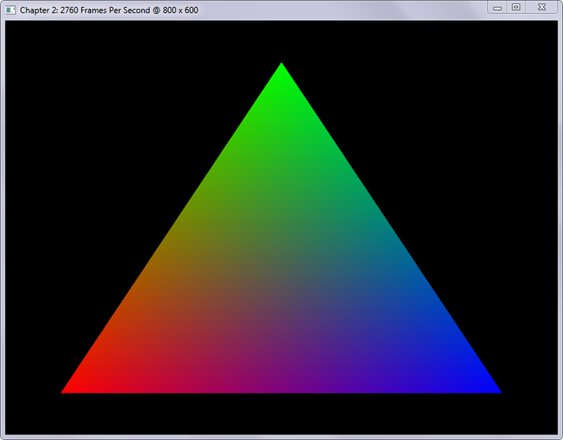
Now that you have all of the required content, compile your program and run it. The output of your program should look like the following screenshot:
Step-By-Step
We've added quite a bit of new code and many new OpenGL function calls that we haven't used before -- let's explore exactly what we've done.
The first thing we did was change the title of the window that we created by
modifying the WINDOW_TITLE_PREFIX pre-processor definition, so no big change
there.
Next, we declared a few new global variables to hold the identifiers created for the shaders and buffer objects that we'll be creating.
A Brief Introduction to Shaders
While we will be discussing shaders in much detail in a future chapter, some basic knowledge of them is useful before we go any further. Shaders comes up frequently, whether it is in talks about graphics hardware or rendering software, the word "shader" is usually prevalent.
In the context of OpenGL (as well as Direct3D), a shader is program that runs on the graphics hardware. OpenGL expresses a shader program through a C-like programming language called the OpenGL Shading Language, or GLSL. In the code above, we've already created two GLSL programs, one for per-vertex processing, and one for per-fragment processing.
A vertex shader operates on a per-vertex basis, modifying the vertex's attributes passed in. A fragment shader operates on a per-fragment, modifying the final color of a pixel.
The Vertex Shader
Let's take a quick look at the Vertex shader:
The first line of our vertex shader program is a GLSL pre-processor definition
denoting which version of GLSL the program requires; in our case this is version
400, corresponding with GLSL version 4.00. The #version pre-processor
definition is required to access the feature set associated with that specific
GLSL version. If you don't provide it, the GLSL version will fall back to
version 1.10; the last version of GLSL where the #version definition was not yet
required.
The next line is a bit more puzzling, but not too hard to understand. The name
of the variable on this line is in_Position, containing the vertex's
positional data stored in a four-dimensional vector, denoted by the vec4 data
type. The keyword in defines that this is a parameter into this vertex shader,
so we'll need to provide it through our OpenGL program. This is where the layout
qualifier comes into play at the beginning of the line: layout(location=0).
We'll discuss this coupling of GLSL and vertex information from our program in
the walkthrough of the CreateVBO function below.
The next line is almost the same as the line before, except that the variable's
name is in_Color, and contains the vertex's color information stored in four
color-channels using data type vec4.
The next variable declaration is that of ex_Color, containing the final vertex
color to be copied to the next shader stage. To denote that this variable is an
output of our shader, we prefix it with the keyword out. The prefix ex_ is
used in this book to denote a variable that is exchanged between different
shaders.
Much like a C-program, a GLSL shader program must contain a main entry
function, but unlike C, the GLSL main function does not return anything and
takes in no parameters. The main functions of the GLSL shaders in this chapter
are simple for demonstration purposes; in subsequent chapters, we'll explore
shaders that are more complex.
The first line of our main function copies the value that we passed into
in_Position into gl_Position, the final vertex position passed on to
subsequent shader stages. You may have noticed that we don't declare
gl_Position anywhere; this is because it is a built-in variable. Any
transformation that you apply to gl_Position will reflect in your final
rendering. For example, we will use this variable extensively in future chapters
to relay the vertex's final position after we apply perspective projection
calculations to the vertex.
The last line of the main function assigns the final vertex color to our
ex_Color output variable. Since ex_Color is marked as out, we will be able
to use its value in the next shader stages. This is where we enter the fragment
shader stage of our GLSL program:
The Fragment Shader
The ex_Color parameter is not an output in this shader, but an input instead.
This is because we have copied the output variable of the same name from the
vertex shader into the fragment shader. The fragment shader's only output
parameter is the out_Color variable, containing the final color of the
fragment that this shader processed. The final color assigned to out_Color is
equal to the color passed into the ex_Color variable.
Object Creation
We'll need some new functions for creating and destroying the buffer objects and
shaders, so we declared five new functions. We also added calls to the
CreateShaders and CreateVBO functions in the Initialize function
definition, after OpenGL and GLEW were initialized.
Since we're creating objects in this chapter, we need a method of destroying
these objects properly as well. This is achieved by tying a function call back
to glutCloseFunc, in our case, Cleanup, which calls both DestroyShaders
and DestroyVBO. The Cleanup function is called by FreeGLUT right before the
OpenGL context is destroyed, so we can do our resource cleanup correctly and
without any problems.
Creating the Buffer Objects (CreateVBO)
Since shaders are described in much detail in chapter four, we'll solely focus
on the creation of the buffer objects in the CreateVBO function.
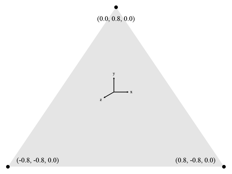
Before we create our vertex buffer object, we must first define the vertices of the geometrical object that we're creating. Vertices are points in three-dimensional space that define the corners of a geometrical object, in our case the triangle. Vertices have three dimensions, namely X, Y, Z, and W, much like points on a graph:
- The first dimension, X, represents movement along the horizontal axis
- The second dimension, Y, represents movement along the vertical axis
- The third dimension, Z, represents depth, meaning how far away or nearby an object is
W, our fourth dimension has nothing to do with physics, where time represents the fourth dimension, rather, it has everything to do with something called homogeneous coordinates which we'll explore when we cover three-dimensional geometry, matrices, and projection in a near future chapter. For now, make sure that the value of W is always 1.0, and take its purpose on faith until we describe it in more detail.
In OpenGL, the components of a vertex are represented through floating point numbers: since a triangle has three vertices, and a vertex has four dimensions, we must create twelve floating point numbers to represent our triangle. The array named Vertices contains the following X, Y, and Z coordinates:
Since vertices only define coordinates, we'll need to define another array
containing RGBA color values. This array is called Colors and defines the
colors for each of our vertices. Since RGBA colors have four components, and we
need to color three vertices, our array contains twelve floating point values.
In order, the colors we define in the array are Red (1.0, 0.0, 0.0, 1.0), Green
(0.0, 1.0, 0.0, 1.0), and Blue (0.0, 0.0, 1.0, 1.0).
The last value of an RGBA color is called Alpha, which controls the transparency of a given color where 0.0 equals 100% transparency, and 1.0 equals 100% opacity.
Next, we define ErrorCheckValue, a variable we use at the end of the function
for error checking purposes. The variable is initialized with the value returned
by a call to glGetError, which retrieves the last error set by OpenGL. We call
this function simply to un-set any errors that may have been set up to this
point, but we discard the value returned by this call.
Vertex Array Objects (CreateVBO)
The first function of interest in CreateVBO is glGenVertexArrays which
generates Vertex Array Objects in the GPU's memory and passes back their
identifiers:
Its first parameter n describes the amount, or number of Vertex Arrays to
generate. After they are generated, their identifiers (or "names" in the OpenGL
documentation) are stored in the arrays parameter, which must be an array of
n elements. In our case, we only have a single Vertex Array Object, so we pass
in the number one to n and the address of the VaoId variable.
So what is a Vertex Array Object?
A Vertex Array Object (or VAO) is an object that describes how the vertex
attributes are stored in a Vertex Buffer Object (or VBO). This means that the
VAO is not the actual object storing the vertex data, but the descriptor of the
vertex data. Vertex attributes can be described by the glVertexAttribPointer
function and its two sister functions glVertexAttribIPointer and
glVertexAttribLPointer, the first of which we'll explore below.
Generating Vertex Buffers (CreateVBO)
Now we're getting to the core of the CreateVBO function and we start
generating buffers by a call to glGenBuffers, which generates our buffers in
the GPU's memory. Here's its function prototype, retrieved from the OpenGL SDK
documentation:
Its first parameter, n, is the number of buffers requested. Once n
buffers have been generated, their identifiers (also referred to as "names" in
the OpenGL documentation) are stored in the array buffers, the function's
second parameter. buffers must be a GLuint array of n elements.
In our case, we request one buffer to be generated, and its identifier stored in
VboId. The generated buffers are of an undefined type until they are bound to
a specific target.
Binding Vertex Buffer Objects (CreateVBO)
Buffers can be bound to several different targets, in our case
GL_ARRAY_BUFFER, which signifies that the data provided contains vertex
attributes. The target is bound to the buffer with a call to glBindBuffer,
which takes the target type as its first parameter, and the buffer's identifier
(returned from glGenBuffers) as the second:
Not only does glBindBuffer bind the buffer to the specified target, it also
activates the current buffer object as the target. This means that any
buffer-related operations that involve the specified target will be executed on
the buffer identified by the buffer parameter until another buffer is bound
with a call to glBindBuffer. In our code, the buffer parameter is set to the
value stored in VboId by glGenBuffers.
Now that the buffer is bound, we can copy our vertex data over to the GPU's
memory. This is achieved by making a call to glBufferData:
The target parameter is once again set to GL_ARRAY_BUFFER to signify that we
are copying data to the currently activated buffer with this target type, in our
case the buffer identified by the value stored in VboId.
The size parameter is set to the size in bytes of our Vertices array. As you
can see from the function prototype above, the data is provided as a void
pointer type through parameter data, which means that you can upload any data
to the GPU's memory as long as you can provide their size. In our case, this
data are an array of floating point numbers, but it could easily be an array of
bytes, or an array of integers for that matter.
The usage parameter is set to GL_STATIC_DRAW, which signified to OpenGL that
the data uploaded to the memory will not be modified (static) and used for
image generation purposes (draw). GL_STATIC_DRAW is not the only usage type
that can be supplied to this function, and we will explore several other usage
types during the course of the book, but for now, we're not modifying the
triangle.
Setting Vertex Attributes (CreateVBO)
Even though all of our data now resides in the GPU's memory, OpenGL still
doesn't know what types of data these are; this is where the
glVertexAttribPointer function comes into play whose prototype looks like
this:
glVertexAttribPointer provides OpenGL with all of the necessary metadata to
use the block of raw data that we've uploaded to the GPU's memory using
glBufferData.
The first parameter that we provide to glVertexAttribPointer is index, which
is a user-maintained number. This number is not generated by a function call of
any kind, but must be maintained by you.
If you recall from our GLSL introduction at the beginning of the chapter, there
was a layout qualifier that we didn't discuss. This index parameter is used to
identify those parameters marked with a layout qualifier in a GLSL shader
program. For example if we changed the index parameter to 18, we must also
update the GLSL shader's layout qualifier's location argument to 18:
Has a 1:1 association with:
As you can see, we're describing the in_Position variable with
glVertexAttribPointer by having four floating point components, which
corresponds to the definition of a vec4 datatype: "vec4 - a four-component
floating-point vector."
You can create many vertex attributes, as long as you keep their
index values less than the value of
GL_MAX_VERTEX_ATTRIBS.
The next parameter is size, and unlike the size parameter that we used in
our call to glBufferData, this one does not represent the size of the data in
bytes, but rather the amount of components that make up a vertex. In our
case, the size parameter is set to 4, signifying the X, Y, Z, and W components
of our vertices.
To calculate the size in bytes of each component, OpenGL needs to know the
data-type of each component passed to the type parameter, in our case
GL_FLOAT since each component is a floating point number.
If the values in our vertex array were not floating point values but integer
values, we'd have the option of normalizing the values to a certain range before
using them by passing GL_TRUE into the normalized parameter. If the values
provided were signed integers, the values would be normalized to the [-1, 1]
range, and if they were unsigned, they would be normalized to the [0, 1] range.
For example, if we'd pass in an unsigned byte with a value of 255, the resulting
floating point value would be 1.0. In our program, the values passed are
normalized floating point numbers so the value passed to normalized is
GL_FALSE.
Normalization is useful since it allows us to upload many types of data without having to worry about converting and clamping the supplied values ourselves. This is especially handy for color data, which are often represented as unsigned bytes or integers.
It is possible to upload user-defined data structures using glBufferData, but
OpenGL will have to know where the significant data in a structure ends and
where the next starts. This is achieved by passing a value into the stride
parameter, which signifies how many bytes are between the significant blocks of
data. In our case this is zero since we use a packed array, but there are many
cases where this could be useful. By utilizing the stride parameter, a single
buffer object may be used for many different attributes by calling
glVertexAttribPointer with different stride and pointer values.
Last but not least, there is the pointer parameter. When the current target is
set to GL_ARRAY_BUFFER, this parameter is a numerical offset in bytes in the
block of data supplied in glBufferData to where the significant data starts.
As with the stride parameter, this parameter is also important if the data you
upload to the GPU's memory contains many values for different purposes (i.e.
combining color and vertex data in a single data type). In our case, the
stride and pointer parameters are both set to zero since the data we provide
are sequential in nature.
We explore the possibilities of the stride and pointer parameters in the last section of this chapter where we upload a custom data structure to the GPU's memory.
When we're done providing vertex attributes, the attribute can be enabled with a
call to glEnableVertexAttribArray and passing in the index also used as the
first parameter in glVertexAttribPointer, this allows the vertex data to be
used for drawing purposes. When you're done drawing the buffer object, a call to
glDisableVertexAttribArray should be made.
Since we're only drawing a single triangle in our program, the
glEnableVertexAttribArray and glDisableVertexAttribArray calls are made in
the CreateVBO and DestroyVBO functions, respectively. This means that the
vertex attributes created in CreateVBO are enabled throughout the execution of
the entire program; this would normally not be the case if there was more than a
single object to draw.
Setting the Color Data (CreateVBO)
As you can deduce from the code sample, setting the color data is done in the
exact same manner as setting the vertex data. In fact, the only difference is
the buffer identifier passed to glBindBuffer, the data passed into the
glBufferData function, and the vertex attribute index used.
Checking for Errors (CreateVBO)
After the color data is set, we check if there were any errors by checking if an
error flag was set by calling glGetError. If there was, we translate the value
returned from this function with a call to gluErrorString, which returns the
human-readable version of the code returned, and exit the program with an error
code.
Creating the Shaders (CreateShaders)
Much like a C or C++ program, a GLSL shader program needs to be compiled and linked before it can be executed.
First, we must create shader objects for both our vertex shader, this is
accomplished by calling the glCreateShader function:
This function tells the OpenGL to generate a new shader object of shaderType
and return its identifier. In our program we store this identifier in variable
VertexShaderId. Now that we have our shader object, we can copy our GLSL
source code to OpenGL for compilation. This is done with a call to
glShaderSource:
This function copies the source code in the string specified by parameter
string and associates it with the shader object identified by parameter
shader, which is the identifier returned by glCreateShader, in our case
VertexShaderId.
The count parameter specifies how many strings are present in the string
parameter, in our case this is 1 since VertexShader is one long string. The
last parameter length is an array of integers denoting the lengths of the
strings in the string parameter. You can usually leave this parameter at NULL
if you use normal null-terminated strings, as in our case.
Now that we have our shader's source code in memory, we have to compile it
before we can get any further. This is done with the glCompileShader function:
This is a fairly straightforward function which takes in the shader's identifier
as its shader parameter.
This whole process from glCreateShader to glCompileShader is repeated for
the fragment shader. Now that we've compiled the individual shaders, we need to
combine them in a shader program object. To do this, we must generate a program
object:
This function returns an identifier which we store in ProgramId and takes in
no parameters. You can think of a shader program object as a regular executable:
it is composed of several compiled objects linked together to form a whole. To
attach the shaders to the program we use the glAttachShader function:
The syntax for this function couldn't be simpler in that it takes in the
identifier for the the shader program object in its program parameter and the
identifier of the shader in the shader parameter. The last step before we can
use our shader program is linking:
Another almost self-explanatory function which takes in the shader program
object's identifier and doesn't return a value. After this whole process
completes, we can use our new shader program by calling glUseProgram:
Which takes in the shader program object's identifier and makes it current. The
current program remains active until glUseProgram is called with another
shader program object's identifier.
Drawing the VBO (RenderFunction)
We draw the contents of the VBO to the screen in RenderFunction by making a
call to glDrawArrays, which operates on the vertex attribute arrays that are
enabled for drawing with a call to glEnableVertexAttribArray, our color and
vertex arrays from CreateVBO. The OpenGL function glDrawArrays has the
following prototype:
The first parameter, mode, specifies the type of array data that's going to be
drawn to the screen with this function call. In our case, this value is set to
GL_TRIANGLES, but we'll soon explore some more options for this parameter.
The second parameter, first, specifies the first index of the enabled vertex
attribute arrays that we want to draw. The last parameter, count, specifies
how many of the enabled indices to draw. In our case these parameters are set to
zero for first, signifying the index of the vertex position data, and three
for count, signifying that there are three vertices to draw.
Cleanup
After the program exits because of a user action, the CleanUp function is
called by FreeGLUT to dispose of some of our generated objects.
Destroying the Shaders (DestroyShaders)
There are a few function calls required to clean up shaders, but before we can clean up, we'll have to tell OpenGL to stop using our shader program by calling:
By passing zero as the program parameter, we tell OpenGL to stop using the
shader program. Now that our shader program is no longer being used, we can
safely detach the fragment and vertex shaders from our program object by calling
glDetachShader:
This function is the exact opposite of glAttachShader and expects the exact
same parameters: *it takes in the identifier for the the shader program object
in its program parameter and the identifier of the shader in the shader
parameter.
Since the shaders are now no longer in use by the shader program, we can safely
delete them by calling glDeleteShader:
Which simply takes in the shader's identifier, in our case VertexShaderId and
FragmentShaderId. After the shaders have been detached from the program, and
the program is no longer in use, we can also safely delete the shader program:
Which takes in the shader program object's identifier, in our case ProgramId.
Cleanup (DestroyVBO)
Now that you know how to properly create buffer objects and draw them, it's time
to learn how to destroy them, so let's take a quick look at DestroyVBO.
Much like in the CreateVBO function, we define an ErrorCheckValue variable
and populate it by calling glGetError to clear any errors that were previously
set by OpenGL.
Next, we disable the vertex attributes that we enabled in CreateVBO in reverse
order of creation by making two calls to glDisableVertexAttribArray with the
appropriate indices provided.
We make a call to glBindBuffer like before, however, this time we set the
buffer parameter to zero to indicate that no buffers should be tied to the
GL_ARRAY_BUFFER target. This allows us to safely delete the buffers by calling
glDeleteBuffers, whose prototype looks like this:
As you may have noticed, this call is similar to glGenBuffers since it takes
in the exact same parameters, but does the exact opposite by deleting instead of
generating.
At this point, it is safe to exit the program, but first we check for errors with our familiar error checking setup. If an error is detected, write the error string to the command line and exit the program with an error code.
Creating a Rectangle
In this section, we'll explore a few of the methods that we can use to define a rectangle in OpenGL. All of these methods use triangles as the fundamental building blocks for constructing the rectangle.
Using GL_TRIANGLES
Much like in our first exercise, this sample uses triangles to construct
geometry. Create a copy of chapter.2.1.c, name it chapter.2.2.c and open it
up. let's make some changes to our program in order to draw our rectangle:
Change the Vertices array in CreateVBO to contain six total vertices, making
the total number of elements in this array twenty-four:
Similar to the Vertices array, also change the Color array to contain twenty-four elements because of its six RGBA colors:
And last but not least, change the DrawArrays command in our RenderFunction to draw six vertices instead of three:
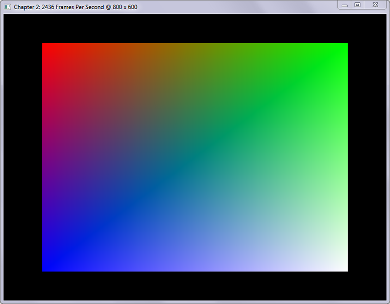
The output of your program should now look like this:
Step-By-Step
We basically did the same thing as in the first section of this chapter by creating not one, but two triangles inside a single buffer object. We've set up six vertices that define the following X, Y, and Z coordinates:
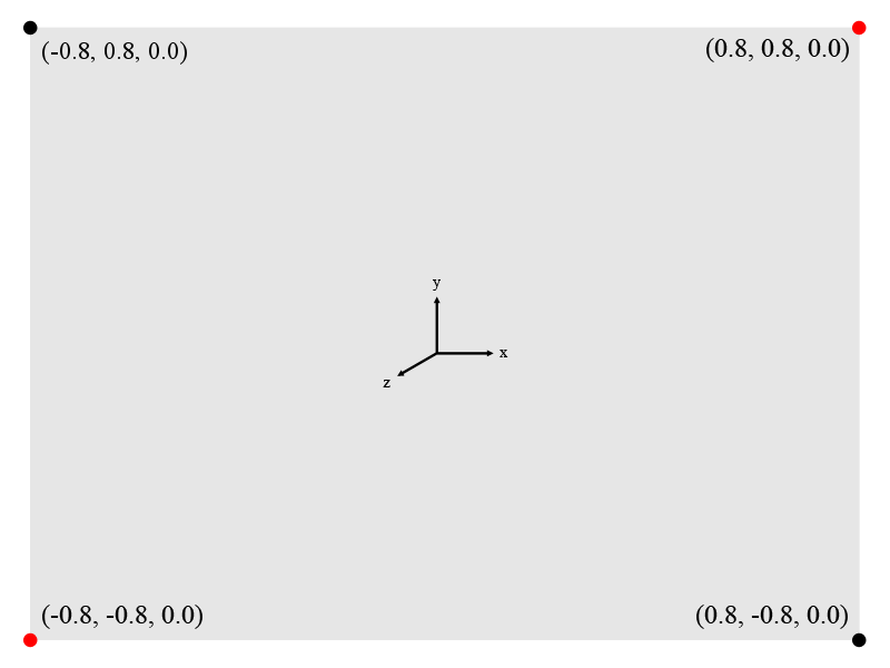
The highlighted (red) coordinates signify vertices that are used in both triangles, but even though the same vertices appear in both triangles, each triangle has to redefine this vertex. This is the same for the color array, which also contains duplicate values since there is one color for each vertex.
Adding more triangles this way doesn't take much modification, but causes unnecessary duplication of data when the triangles are consecutive in nature as ours are.
Using GL_TRIANGLE_STRIP
Create a copy of chapter.2.1.c named chapter.2.3.c and open it up for editing.
Change the Vertices array in the CreateVBO function to contain the following
four vertices:
Change the Colors array in the same function to this:
And lastly, change the glDrawArrays function call in RenderFunction to the
following:
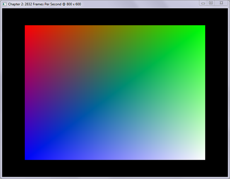
The output of your program should like the following screenshot:
Step-By-Step
The example above uses a method called triangle strips to construct geometry,
which allows us to reuse vertices to construct new triangles. As you may have
noticed, the rendered image is exactly the same as the one rendered with
GL_TRIANGLES.
Even though the output is the same, the GL_TRIANGLE_STRIP method significantly
reduces the amount of vertices used and is perfect in situations where triangles
are constructed consecutively and vertices can be reused. The image below
illustrates exactly how GL_TRIANGLES and GL_TRIANGLE_STRIP differ in their
methods of triangle creation:
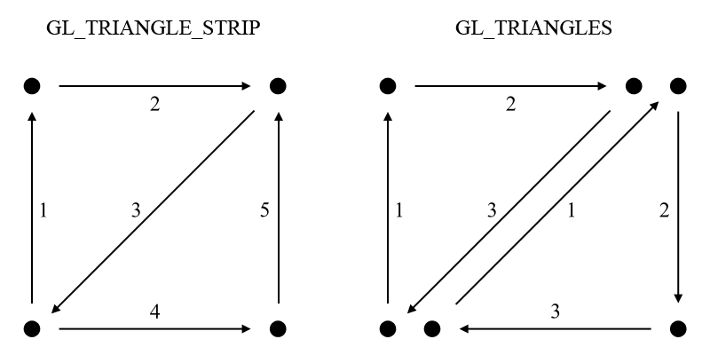
Both methods create an initial triangle, but the GL_TRIANGLE_STRIP mode simply
adds one more vertex to create the next triangle, while the GL_TRIANGLES mode
requires the creation of an entirely new triangle.
Vertex Attributes
The aim of this section is to show you how you can upload your own custom data structures to the GPU's memory and still access its data correctly.
Create a copy of chapter.2.1.c named chapter.2.4.c, and open it up in your
editor. Add the following structure definition right below the
WINDOW_TITLE_PREFIX definition:
Remove the ColorBufferId variable declaration, so the section looks as follows:
Next, replace the entire CreateVBO function with the following code:
And finally, remove the following line from the DestroyVBO function:
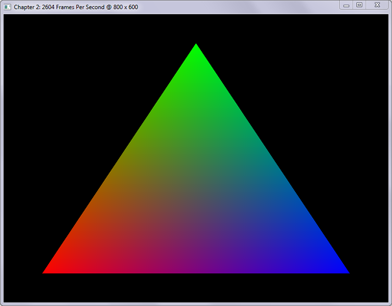
The output of this program is exactly the same as the output of the very first exercise of this chapter, a single triangle:
Step-by-Step
The main thing that you should take away from this section is that we no longer
use two separate buffers for our vertices' color and position data. Instead, we
utilize our user-defined structure Vertex and upload an array of those to the
GPU's memory containing the same data as in the first exercise of this chapter.
The structure itself contains two arrays of four floating point numbers,
Vertex.XYZW representing the position data and Vertex.RGBA representing the
color channels.
We removed ColorBufferId and instead used BufferId for both the color and
vertex buffers, since we no longer use multiple buffers to represent a single
object. This becomes apparent in the CreateVBO function where we now call
glGenBuffers asking only for a single buffer in return.
The next major change is that we only call glBindBuffer once and bind both of
the vertex attributes to this buffer. Next, we upload the entire Vertices
array into the GPU's memory, containing our three instances of Vertex.
Stride and Pointer
As mentioned in the first exercise of this chapter, setting the stride and
pointer parameters of the glVertexAttribPointer function allows us to pack
many different data into a single buffer. By supplying these parameters, OpenGL
can determine the position of the next block of memory it needs to use.
The stride parameter defines the amount of bytes required to get from one
vertex to the next, which is simply the size in bytes of our Vertex structure
stored in the VertexSize constant. This value is the same for both attributes
since they both operate on the same data structure.
The pointer parameter is zero for the position-data, since it is the first
array in our data structure and does not require an offset to access. The color
data, however, does need an offset, which is set to the size of the
Vertex.XYZW array in bytes since this is the block of data required to skip to
get to the color data.
Much of the functionality remained the same in this exercise, but most importantly, the format of the data changed significantly.
Conclusion
We drew our first geometry onto the screen and learned many new things in this chapter, including how to construct basic geometry using buffer objects.
Now that we have a basic understanding of buffers, shapes, and vertices, it's time to expand on our knowledge with array indices in the next chapter.
You can find the source code for the samples in this chapter here.

